


Study on Calculation Method of Butterfly Valve Shaft Considering Fatigue Effect
-
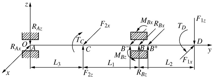
摘要: 阀轴是蝶阀的关键受力部件,传统方法基于扭矩计算阀轴应力而未充分考虑弯矩的影响,应用于大型蝶阀设计存在一定的风险。本文分别将滑动轴承支反力简化为均布载荷和集中力,与变形协调方程相结合,提出了一种新的阀轴弯扭组合数学模型,采用有限元方法和实验方法对数学模型进行了验证;最后,分别采用冯·密斯应力和Goodman准则对阀轴应力进行评定,得到阀轴设计安全系数。结果表明,本文提出的阀轴计算数学模型与评估方法具有较高的精度,对改进蝶阀设计方法具有重要指导意义。Abstract: The valve shaft is the key force component of butterfly valve, the traditional calculation method of the valve shaft stress is based on the torque which not fully considers the bending moment effect, so there exist the certain risks for applying to the large butterfly valves design. In this paper, the sliding bearing constraint force is simplified to uniform distributed-load or concentrated force, by combining with the compatibility equation, then a new model for valve shaft bending and torsion combination is proposed, thus finite element and experimental method is used to verify the present model. Finally, the valve shaft stress is evaluated with the Von Mises stress and Goodman criteria respectively, and the safety factor of the valve shaft design is obtained. The results show that the given model and evaluation method of the butterfly valve shaft calculation perform with high precision, which are of the important guiding significance to improve the design method of butterfly valve.
-
Key words:
- butterfly valve /
- valve shaft stress /
- fatigue life /
- bending and torsion combination
-
表 1 蝶阀运行条件与结构参数
物理量 数值 物理量 数值 阀门直径 0.9 m 工作压力 0.7 MPa 介质流速 8 m/s 介质温度 20 ℃ 阀轴轴径 11 cm 蝶板重量 379.5 kg 一偏心 8.8 cm 二偏心 1.6 cm 重锤大小 0.7 t 开阀油压 8 MPa  下载: 导出CSV
表 2 各危险工况载荷表
力矩/(N·m) 危险工况 1 2 3 重锤力矩 6 625.8 6 217.1 6 625.8 一偏心力矩 98 74.5 98 二偏心力矩 3 257.5 16 276.2 21 247.2 轴承摩擦力矩 1 676.8 2 456.9 4 867.7 填料摩擦力矩 214.2 215.6 215.1 密封面力矩 4 594.2 - - 动水力矩 - 6 021.1 -
下载: 导出CSV
表 4 各危险工况主动力
分力 危险工况1 危险工况2 危险工况3 F1x/N 67 752.4 112 617.7 318 086.3 F1z/N 1 859.6 96 357.1 1 859.6 F2x/N 20 370.5 12 730.6 0 F2z/N 17 323.8 12 860.1 41 314.4
下载: 导出CSV
表 5 危险工况下轴套支反力和支反力矩
参数 危险工况 1 2 3 RBx/N 57 475.8 106 195.3 318 086.3 RBz/N -6 880.1 89 869.3 -18 983.0 RAx/N 10 093.9 6 308.2 0 RAz/N 8 584.2 6 372.4 20 471.9 MBx/(N·m) 869.3 11 092.7 1 789.8 MBz/(N·m) -8 234.4 -12 876.4 -34 989.5
下载: 导出CSV
表 6 各危险工况下载荷与应力
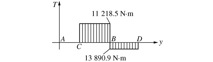
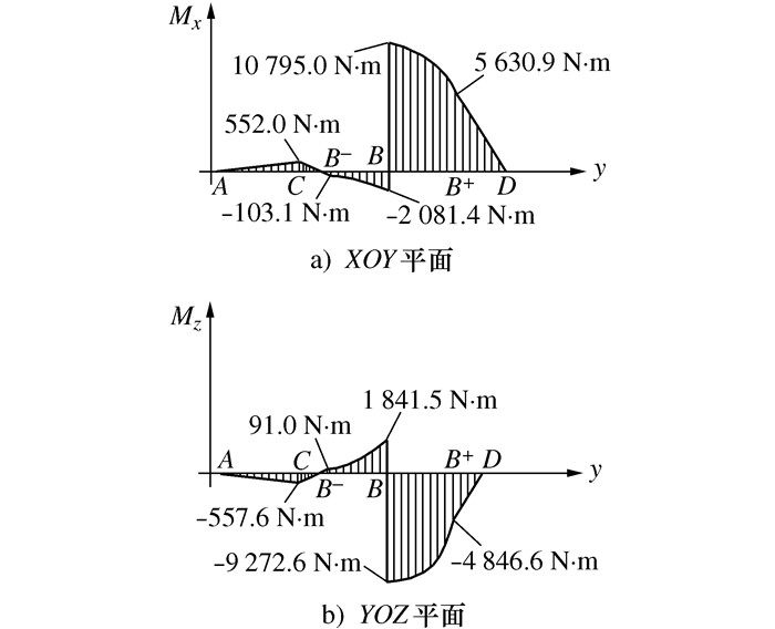
危险工况 位置 Mz/(N·m) Mx/(N·m) T/(N·m) σca/MPa 1 B 583.4 6 590.6 -1 892.4 52.0 2 B -4 846.6 10 795 2 672.5 110.2 3 B+ -93.0 15 904 5 083.3 126.3
下载: 导出CSV
表 8 蝶阀主要材料性能
材料 弹性模量/MPa 泊松比 密度/(kg·m-3) 屈服极限/MPa 抗拉强度/MPa Q345A 206 0.28 7 850 345 470.0 2Cr13 230 0.25 7 750 440 687.5
下载: 导出CSV
表 9 各零件接触关系
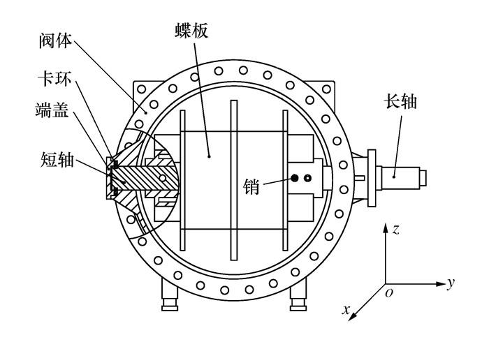
销 短轴 长轴 蝶板 阀体 端盖 卡环 销 - 无摩擦 无摩擦 绑接 - - - 短轴 - - 无摩擦 有摩擦 - 无摩擦 长轴 - 无摩擦 有摩擦 - - 蝶板 - - - - 阀体 - 绑接 无摩擦 端盖 - 无摩擦 卡环 -
下载: 导出CSV
表 10 各工况下蝶阀载荷及方向
危险工况 压力/MPa 密封面力矩/(N·m) 油缸力矩/(N·m) 重锤力矩/(N·m) 动水作用力/N 动水力矩/(N·m) 静水力矩/(N·m) 1 0.213(-x) 4 594.3(y) 28 369.0(-y) 6 625.8 (y) - - - 2 0.710(-x) - - 6 217.1 (y) 294 024(-x) 6 021.1(y) - 3 1.000(x) 4 594.3(y) - 6 625.8 (y) - - 315.6(y)
下载: 导出CSV
表 11 各计算方法阀轴Von Mises应力
MPa 计算方法 危险工况1 危险工况2 危险工况3 均布载荷理论 52.03 110.23 126.29 集中力理论 58.40 126.00 126.30 有限元 58.81 128.38 102.76
下载: 导出CSV
-
[1] 童成彪. 蝶阀的优化设计和流场研究[D]. 长沙: 湖南大学, 2010TONG C B. The optimization design and flow field analysis for butterfly valve[D]. Changsha: Hunan University, 2010 (in Chinese) [2] 张清双, 吴斌彬, 茅岭峰. 高温高压四偏心蝶阀设计及零件强度计算[J]. 阀门, 2019(1): 1-6 https://www.cnki.com.cn/Article/CJFDTOTAL-FAME201901001.htmZHANG Q S, WU B B, MAO L F. Calculation for the design of the quadruple eccentric butterfly valve for high temperature and high pressure, as well as the Parts' strength[J]. Valve, 2019(1): 1-6 (in Chinese) https://www.cnki.com.cn/Article/CJFDTOTAL-FAME201901001.htm [3] 刘长亮, 丘锦萌, 韩健. 蝶阀流固耦合计算与分析[J]. 阀门, 2015(2): 4-6 https://www.cnki.com.cn/Article/CJFDTOTAL-FAME201502009.htmLIU C L, QU J M, HAN J. Coupled Fluid-structure calculation of a butterfly valve[J]. Valve, 2015(2): 4-6 (in Chinese) https://www.cnki.com.cn/Article/CJFDTOTAL-FAME201502009.htm [4] 谢金宏. 双偏心蝶阀开裂失效分析[J]. 金属热处理, 2019, 44(S1): 60-63. https://www.cnki.com.cn/Article/CJFDTOTAL-JSRC2019S1018.htmXIE J H. Double eccentric butterfly valve cracking failure analysis[J]. Heat Treatment of Metals, 2019, 44(S1): 60-63 (in Chinese) https://www.cnki.com.cn/Article/CJFDTOTAL-JSRC2019S1018.htm [5] 余煜哲, 刘忠伟, 邓英剑. 复杂服役环境下高压阀门疲劳可靠性数值分析[J]. 湖南工业大学学报, 2018, 32(6): 45-50 doi: 10.3969/j.issn.1673-9833.2018.06.008YU Y Z, LIU Z W, DENG Y J. Numerical analysis on fatigue reliability of high pressure valves in complex service condition[J]. Journal of Hunan University of Technology, 2018, 32(6): 45-50 (in Chinese) doi: 10.3969/j.issn.1673-9833.2018.06.008 [6] 倪平. 蝶阀动水力和动水力矩计算式的探讨[J]. 阀门, 2016(5): 4-6, 41 https://www.cnki.com.cn/Article/CJFDTOTAL-FAME201605002.htmNI P. The analysis of equations for butterfly valve hydrodynamic force and hydrodynamic torque[J]. Valve, 2016(5): 4-6, 41 (in Chinese) https://www.cnki.com.cn/Article/CJFDTOTAL-FAME201605002.htm [7] 沈阳阀门研究所《阀门设计》编写组. 阀门设计[M]. 沈阳: 沈阳阀门研究所出, 1976Shenyang Valve Research Institute. Valve design[M]. Shenyang: Shenyang Valve Research Institute, 1976 (in Chinese) [8] 徐翠翠, 张静. 大口径循环水蝶阀不同蝶板形式的受力分析及优化[J]. 通用机械, 2018(6): 59-63 doi: 10.3969/j.issn.1671-7139.2018.06.017XU C C, ZHANG J. Force analysis and optimization of different butterfly plate forms of large-diameter circulating water butterfly valve[J]. General Machinery, 2018(6): 59-63 (in Chinese) doi: 10.3969/j.issn.1671-7139.2018.06.017 [9] 濮良贵, 陈国定, 吴立言. 机械设计[M]. 10版. 北京: 高等教育出版社, 2019PU L G, CHEN G D, WU L Y. Machine design[M]. 10th ed. Beijing: Higher Education Press, 2019 (in Chinese) [10] CARABALLO S C, RODRÍGUEZ J L O, RUIZ J A L, et al. Optimization of a butterfly valve disc using 3D topology and genetic algorithms[J]. Structural and Multidisciplinary Optimization, 2017, 56(4): 941-957 doi: 10.1007/s00158-017-1694-4 [11] KWAK H S, SEONG H, KIM C. Design of laminated seal in cryogenic triple-offset butterfly valve used in LNG marine engine[J]. International Journal of Precision Engineering and Manufacturing, 2019, 20(2): 243-253 doi: 10.1007/s12541-019-00056-6 [12] JEONG S H, CHOI D H, YOON G H. Fatigue and static failure considerations using a topology optimization method[J]. Applied Mathematical Modelling, 2015, 39(3-4): 1137-1162 doi: 10.1016/j.apm.2014.07.020 [13] ROTHGANG S, PACHMANN M, NIGRIN S, et al. The electric supercharger-challenge, conception and implementation[J]. Auto Tech Review, 2016, 5(3): 26-31 doi: 10.1365/s40112-016-1102-2 [14] 罗杨阳, 倪樵, 陈铎民, 等. 吊挂随机振动疲劳影响因素分析[J]. 机械科学与技术, 2016, 35(6): 821-825 doi: 10.13433/j.cnki.1003-8728.2016.0601LUO Y Y, NI Q, CHEN D M, et al. Effect factor analysis of random vibration fatigue of missile hanging[J]. Mechanical Science and Technology for Aerospace Engineering, 2016, 35(6): 821-825 (in Chinese) doi: 10.13433/j.cnki.1003-8728.2016.0601 [15] 金燕, 刘少军, 蒋玉孝. 基于有限元的热机耦合下角接触球轴承疲劳寿命预测[J]. 机械强度, 2018, 40(3): 695-701 https://www.cnki.com.cn/Article/CJFDTOTAL-JXQD201803031.htmJIN Y, LIU S J, JIANG Y X. Fatigue life prediction for row angular contact ball bearings under thermo-mechanical coupling based on fem[J]. Journal of Mechanical Strength, 2018, 40(3): 695-701 (in Chinese) https://www.cnki.com.cn/Article/CJFDTOTAL-JXQD201803031.htm -


 点击查看大图

图(10) / 表(14)
计量
- 文章访问数: 234
- HTML全文浏览量: 105
- PDF下载量: 23
- 被引次数: 0
