


Implementation and Kinematics Calculation of a Modified Canfield Mechanism
-
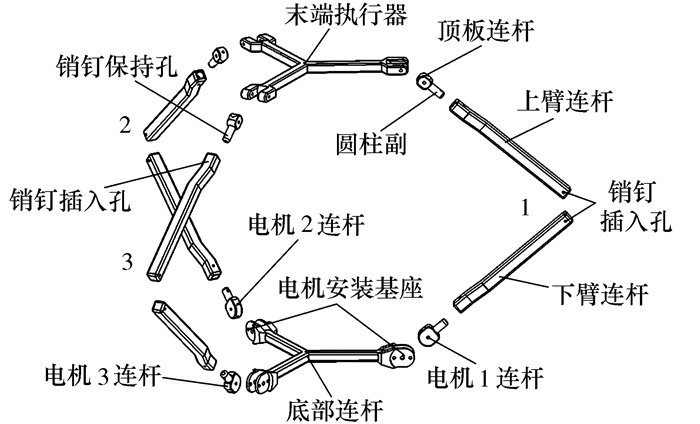
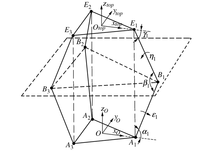
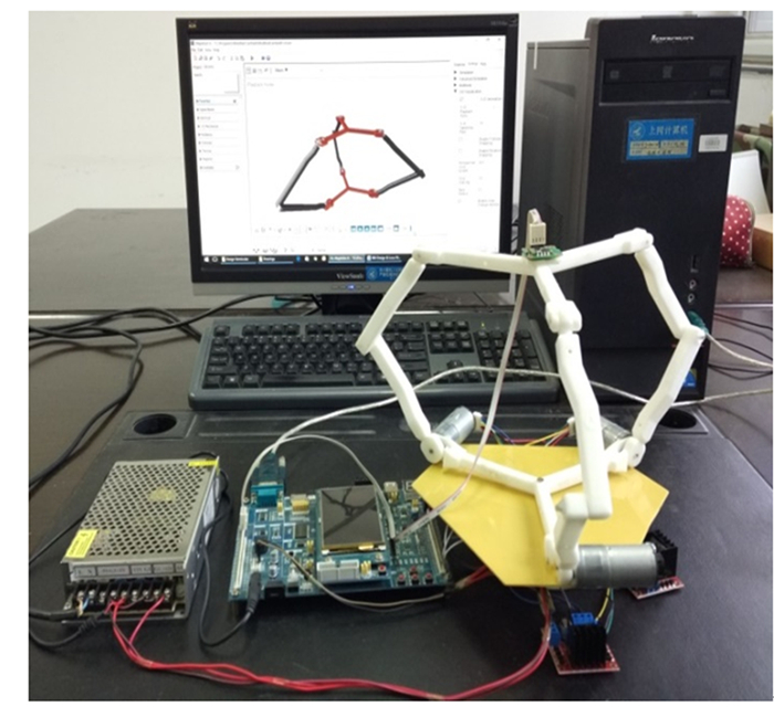
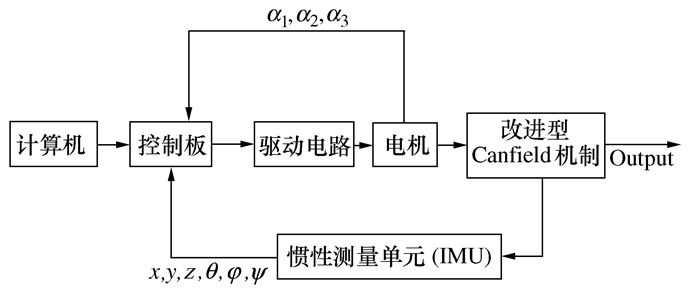
摘要: 设计了一种改进型Canfield机械结构,该机械结构采用旋转副代替移动副,采用扭力弹簧消除了旋转副引入的奇点,减小了结构尺寸,增强了伸缩性能,能实现全半球运动。针对这种设计利用机构的对称性,给出了一种运动学解算的简便方法,在进行运动学解算时不需要考虑奇异性问题,减少了未知数个数,简化了计算。给出了结构3D打印的实物模型及基于模型顶部安装的惯性测量单元(IMU)的模型运动姿态测试方案和带集成光电编码器的直流伺服驱动电机电机转角反馈运动姿态解算方案。对比了基于MapleSIM和Matlab的结构运动仿真计算结果和结构模型实际运动控制实验效果。结果表明,实验和仿真解算数据吻合程度好,验证了所设计结构的合理性和所提出的运动学解算方法的有效性。
-
关键词:
- Canfield结构 /
- 全半球运动 /
- 对称 /
- 运动学 /
- 伺服驱动
Abstract: This paper presents the implementation of a modified Canfield mechanism. Revolute joints are used as active joints instead of prismatic joints, and 3 torsion springs eliminate the singularities caused by the revolute joints. This arrangement is adopted for its usefulness in reducing the size of the structure, improving elongation/contraction restrictions and easily realizing full hemisphere movement. Based on the geometric symmetrical motion of the mechanism around the mid plane, a computationally simple kinematic solution is proposed. The proposed solution reduces not only the unknown numbers of the kinematics calculations but also the singularities in the workspace. The mechanism was implemented on a 3D printed plastic model which has an inertial measurement unit (IMU) mounted on the end-effector. The actuation was provided by a DC motor, and the feedback of the motor and the mechanism was acquired by an optical encoder and the IMU respectively. The simulation results obtained with the MapleSIM and the MATLAB are evaluated experimentally and the comparison results show that the mathematical model agrees with the experimental results.-
Key words:
- Canfield mechanism /
- full hemisphere movement /
- symmetry /
- kinematics /
- servo actuator
-
表 1 运动学解算结果与IMU实测结果对比
输入角度 计算结果 验证结果 α1=45° xtop=0 ψ=0 xtop=-0.88 ψ=-1.21° α2=45° ytop=0 φ=0 ytop=-1.35 φ=-1.34° α3=45° ztop=173.24 θ=0 ztop=174.54 θ=0.81° α1=30° xtop=0 ψ=0 xtop=-0.65 ψ=-0.79° α2=30° ytop=0 φ=0 ytop=-0.28 φ=-1.31° α3=30° ztop=122.5 θ=0 ztop=124.59 θ=0.24° α1=60° xtop=0 ψ=0 xtop=-0.26 ψ=-1.73° α2=60° ytop=0 φ=0 ytop=2.27 φ=-1.23° α3=60° ztop=212.18 θ=0 ztop=213.28 θ=-1.01° α1=30° xtop=31.42 ψ=0 xtop=30.69 ψ=-1.40° α2=60° ytop=0 φ=19.59° ytop=1.81 φ=19.00° α3=60° ztop=182.02 θ=0 ztop=183.56 θ=-0.84° α1=45° xtop=0.06 ψ=0.005° xtop=0.76 ψ=-1.02° α2=30° ytop=26.45 φ=0.03° ytop=28.25 φ=-1.32° α3=60° ztop=169.22 θ=-17.76° ztop=170.04 θ=-18.36° α1=45° xtop=0.06 ψ=0.005° xtop=-0.98 ψ=-0.99° α2=60° ytop=-26.45 φ=0.03° ytop=-24.86 φ=-1.32° α3=30° ztop=169.22 θ=17.76° ztop=171.61 θ=17.81° 注:xtop, ytop, ztop单位为mm。  下载: 导出CSV
-
[1] Gough V E, Whitehall S G. Universal tyre testing machine[C]//Proceedings of the 9th International Technical Congress. London, UK: FISITA, 1962: 117-137 [2] Stewart D. A platform with six degrees of freedom[J]. Proceedings of the Institution of Mechanical Engineers, 1965, 180(1):371-386 doi: 10.1243/PIME_PROC_1965_180_029_02 [3] Kücük S. Serial and parallel robot manipulators-kinematics, dynamics, control and optimization[M]. Croatia: InTech, 2012 [4] Canfield S L, Reinholtz C F. Development of the carpal robotic wrist[M]//Casals A, de Almeida A T. Experimental Robotics V. Berlin, Heidelberg: Springer, 1998: 423-434 [5] Canfield S L, Ganino A J, Salerno R J, et al. Singularity and dexterity analysis of the carpal wrist[C]//Proceedings of ASME Design Engineering and Technical Conferences. Irvine CA, USA: 1996: 96-DETC/MECH-1156 [6] Merriam E G, Jones J E, Magleby S P, et al. Monolithic 2 DOF fully compliant space pointing mechanism[J]. Mechanical Sciences, 2013, 4(2):381-390 doi: 10.5194/ms-4-381-2013 [7] Bashevkin E, Kenahan J, Manning B, et al. A novel hemispherical anti-twist tracking system (HATTS) for CubeSats[C]//Proceedings of 26th AIAA/USU Conference on Small Satellites SSC12-Ⅲ-5. Logan, Utah, USA: AIAA/Utah State University, 2012: 1-8 [8] Khan H M, Yang J H, Khan Tareen S A. Locomotion patterns of a vermicular robot[C]//Proceedings of the 2nd International Conference on Robotics and Artificial Intelligence. Rawalpindi, Pakistan: IEEE, 2016: 152-157 [9] Merlet J P. Parallel robots[M]. 2nd ed. The Netherlands: Springer, 2006 [10] Sosa-Méndez D, Lugo-González E, Arias-Montiel M, et al. ADAMS-MATLAB co-simulation for kinematics, dynamics, and control of the Stewart-Gough platform[J]. International Journal of Advanced Robotic Systems, 2017, 14(4):1-10 http://www.wanfangdata.com.cn/details/detail.do?_type=perio&id=fc7ba7e8b58ecc5fb7f415fe3356d364 [11] Merlet J P. Parallel manipulators, Part Ⅰ: Theory, design, kinematics, dynamics and control[M]. Le Chesnay, France: INRIA, 1987 [12] Craig J J. Introduction to robotics: mechanics and control[M]. 3rd ed. New Jersey USA: Pearson Prentice Hall, 2005 [13] Hammond F L, Howe R D, Wood R J. Dexterous high-precision robotic wrist for micromanipulation[C]//Proceedings of the 16th International Conference on Advanced Robotics. Montevideo, Uruguay: IEEE, 2013: 1-8 [14] Lee K M, Arjunan S. A three-degrees-of-freedom micromotion in-parallel actuated manipulator[J]. IEEE Transactions on Robotics and Automation, 1991, 7(5):634-641 doi: 10.1109/70.97875 [15] Canfield S L, Soper R R, Reinholtz C F. Velocity analysis of parallel manipulators by truss transformations[J]. Mechanism and Machine Theory, 1999, 34(3):345-357 doi: 10.1016/S0094-114X(98)00033-0 -

 点击查看大图
图(5) / 表(1)
计量
- 文章访问数: 302
- HTML全文浏览量: 164
- PDF下载量: 54
- 被引次数: 0
